Enter product details (such as color, size, materials etc.) and other specific requirements to receive an accurate quote.
leave a message
If you are interested in our products and want to know more details,please leave a message here,we will reply you as soon as we can.

Blogs

  • The Structure of Micro Precision Current Transformers
    The Structure of Micro Precision Current Transformers
    Jul 21, 2026
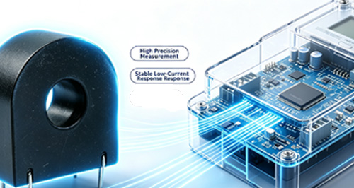
    A Micro Precision Current Transformers consists of a primary winding, a secondary winding, an iron core, insulation between the windings and the core, and a casing.   Micro precision current transformers used to commonly use 1J85 splashed ink alloy wound into a ring-shaped iron core, but thanks to the industry development, currently those Micro Precision Current Transformers mainly use of nanocrystalline core. Common pressure pressed thin strips models include 1k107 and 1k107B. If the Micro precision current transformers performance requirements are not high, silicon steel sheets and ferrites can be used as a replacement choose. The advantage of a ring-shaped magnetic core is that it has no air gap and good magnetic properties. Especially if the winding is uniform during the winding process, the leakage magnetic flux is very small. The insulation between the ring core and the winding is generally achieved by adding a plastic protective shell to the core. The protective shell has two functions, insulation and protection of the core, which the protection of the core is the most important.  The core material is highly sensitive to stress, and its magnetic properties will change when subjected to stress. Adding a protective shell can reduce stress during winding, thus it is important to handle the transformer with care during production. However, ultrafine crystalline materials are already very brittle and require even more protection. After winding the windings, the transformer is encapsulated in the casing. Of course, there will be many inspection processes throughout the entire production process. Micro current transformers are divided into single turn and multi turn types according to the primary winding. The primary winding of a single turn miniature current transformer has only one turn. Rod type: Steel tube copper bars are integrated with the transformer housing through the iron core window (such as micro current transformers used in some electronic meters). Busbar type: The iron core window is retained, and the busbar passes directly through the iron core window. For measuring small currents, the busbar can also be wound around the iron core window for 2 or 3 turns to obtain a smaller current ratio. Multi turn miniature current transformers have multiple turns of primary winding, such as the 103105 series current type miniature voltage transformers. The function of potting adhesive is to encapsulate and insulate, and the commonly used material is epoxy resin+curing agent.
    Quick View
  • The Working Principle of Current Transformer
    The Working Principle of Current Transformer
    Jul 21, 2026
    In the power supply lines, there is a huge difference in current and voltage, ranging from a few amperes to tens of thousands of amperes. For the convenience of secondary instrument measurement, it is necessary to convert the current into a relatively uniform current. In addition, the voltage on the circuit is relatively high, making direct measurement very dangerous. The current transformer plays a role in current conversion and electrical isolation. Previously, most display instruments were pointer type current and voltage meters, so the secondary current of current transformers was mostly in ampere level. Nowadays, most electricity measurement is digitized, and the sampling signal of computers is generally in the milliampere range (e.g. 0-5V, 4-20mA). The secondary current of micro current transformers is in the milliampere range, mainly serving as a bridge between large transformers and sampling.   Miniature current transformers are also known as "instrument current transformers". The term "instrument current transformer" refers to a multi current ratio precision current transformer used in laboratories, generally used to expand the instrument range Principle circuit diagram of current transformer Miniature current transformers work similarly to transformers based on the principle of electromagnetic induction. Transformers convert voltage, while miniature current transformers convert current. As shown in the diagram, winding N1 is connected to the measured current, which is called a set of windings (or primary winding, primary winding); Connect winding N2 to the measuring instrument and become the secondary winding (or secondary winding, secondary winding).   The current ratio between the primary winding power I1 and the secondary winding I2 of a miniature current transformer is called the actual current ratio K. The current ratio of a miniature current transformer when operating at the rated working current is called the rated current ratio of the current transformer, expressed in Kn. Kn=I1n/I2n   Micro current transformers can be roughly divided into measuring current transformers and protective current transformers. A. Measurement current transformer The measuring current transformer is mainly used in conjunction with measuring instruments to measure current, voltage, power, etc. under normal operating conditions of the circuit. The main requirements for measuring micro current transformers are: 1. Reliable insulation; 2. High enough measurement accuracy; When a high current occurs due to a fault in the side line, the transformer should saturate within an appropriate 20% (such as 500% of the rated current) to protect the measuring instrument.   B. Protective current transformer The protective current transformer is mainly used in conjunction with the relay device to provide a signal to the relay device to cut off the faulty circuit in case of short circuit overload or other faults, in order to protect the safety of the power supply system. The working conditions of protective miniature current transformers are completely different from those of measuring transformers. Protective transformers only start working effectively at currents several times or tens of times higher than normal. The main requirements for protective transformers are: 1. Reliable insulation; 2. A sufficiently large accurate limit coefficient, 3. Adequate thermal and dynamic stability. The maximum primary current that the protective transformer can meet the accuracy level requirements under rated load is called the rated accuracy limit primary current. The accurate limit coefficient is the ratio of the rated accurate limit current to the rated primary current. When the current is large enough, the iron core will saturate and cannot reflect the current. The accurate limit coefficient represents this characteristic. The accuracy level of the protective transformer is 5P and 10P, indicating that the allowable error at the rated accuracy limit for one current is 5% and 10%.   When a fault occurs in the circuit, the surge current generates heat and electromagnetic force, and the protective current transformer must withstand it. The effective value of the primary current that a current transformer can withstand without damage within one second in the event of a short circuit in the secondary winding is called the rated short-time current. The peak value of the primary current that the current transformer can withstand without damage in the event of a short circuit in the secondary winding is called the rated dynamic stability current.   Protective current transformers are divided into: Overload protection current transformer Differential protection current transformer Grounding protection current transformer (zero sequence current transformer)   C. Micro voltage transformer Micro voltage transformers, due to size and manufacturing reasons, usually use current type voltage transformers. In fact, it is a current transformer with a rated current ratio of 1 and both primary and secondary currents in milliampere level (e.g. 2mA/2mA):   During operation, the primary winding of the transformer is connected in series with the current limiting resistor R to measure the voltage, and the secondary output is connected to the operational amplifier for I/V conversion (or direct resistance sampling). At this point, the primary current is I1=U (R+r), and the secondary current I2=I1/Kn, where r is the internal resistance of the primary winding and Kn is the rated current ratio.
    Quick View
  • Current Transformer Error
    Current Transformer Error
    Jul 21, 2026
    Reasons for errors In fact, there must be energy loss during the operation of the current transformer, which causes errors in the current transformer. To generate current in the secondary winding, an excitation current I0 is required to excite and generate induced potential and current. The excitation current is provided by the primary winding. The product I0W1 of the excitation current I0 and the number of turns W1 of the primary winding is called the excitation ampere turn or excitation electromotive force. It means that the first winding turns need to be deducted from the example turns before they are transmitted to the first winding, resulting in errors. The error is caused by providing excitation turns.   The error of current transformers consists of two parts: non ratio difference and phase difference. It should be noted that the transformer ratio is the percentage of the secondary current error value to the actual primary current, not the percentage of the rated current. This is different from the method of expressing the error of other general measuring instruments as a percentage of fullness (% F.S). There is no concept of full capacity for current transformers, only the measurement range and rated current. For example, a micro transformer with an accuracy level of 0.1 has an allowable ratio difference of+/-0.1% at 100% rated current and+/-0.4% at 5% rated current. Assuming the rated current is used as the full scale, the allowable ratio difference at 100% rated current is expressed as a percentage of full scale, which is+/-0.1% F.S. The allowable ratio difference at 5% rated current is expressed as a percentage of full scale, which is+/- (0.4x5%/100%)%=+/-0.02% F.S   Error compensation of current transformer Current transformers without compensation have negative specific differences and positive angular differences. The allowable range of error for current transformers at all levels is positive and negative deviation. Therefore, the surplus range of positive and negative deviations can be utilized to improve the accuracy of the transformer. In order to improve the accuracy of transformers, various compensation methods are generally used. In general, due to the small compensation value, it can be considered that the magnetic field of the iron core should not be abstracted. This can be calculated using error superposition. The compensation methods for current transformers include turn compensation, auxiliary iron core compensation, capacitor compensation, etc.   Turn compensation The compensation method for the number of turns of micro current transformers is the simplest, as long as the secondary winding is wound Nx fewer than the rated number of turns. The ratio difference before compensation of the current transformer is replicated, and increasing the current of the secondary winding by fewer turns serves as compensation. The compensation amount is as follows: △f=Nx/(N2-Nx)x100% The ratio difference of the turns compensation team plays a compensating role, and the compensation amount is independent of the secondary load and current size. The compensation turns are generally only a few turns, and the turn compensation should calculate the error between the maximum current low-end secondary impedance and the minimum current high-end secondary impedance. Du Yu's high-precision micro current transformer can compensate for excessive turns even if it only compensates for one turn. At this point, half turn or fractional turn compensation can be used. However, the number of turns of a current transformer is calculated based on the closed circuit passing through the iron core window, and the number of turns of a current transformer is calculated by smashing one by one, without the situation of half a turn. The use of half turn or fractional turn compensation requires the use of auxiliary terminals, such as dual windings, dual iron cores, etc.   Auxiliary iron core compensation The auxiliary iron core compensation has a compensating effect on the contrast difference and angle difference, but the manufacturing process of the auxiliary iron core compensation method is relatively complex.   Capacitor compensation Capacitor compensation can be achieved by directly connecting capacitors in parallel at both ends of the secondary winding of the current transformer. Its contrast difference plays a positive compensation role, and the compensation size is proportional to the X component in the secondary load Z=R+iX, and proportional to the size of the compensation capacitor; It has a negative compensation effect on the cross, and the compensation size is proportional to the R component in the secondary load Z=R+iX, and proportional to the size of the compensation capacitor. Capacitor compensation is an ideal compensation method. In micro precision current transformers, the secondary winding is generally directly connected to the current/voltage conversion of the operation and discharge, and the secondary impedance is basically 0. At this time, the role of capacitor compensation is relatively small. Generally, adding a phase shift circuit in the interpretation of current/voltage conversion can solve the angle difference problem. Users can adjust and calculate the phase shift circuit based on the error data of the voltage reduction in the inspection report of the current transformer that comes with it when it leaves the factory.   There are many compensation methods for current transformers. The compensation of current transformers is an important way to improve the accuracy level of current transformers, and one of the important tasks in designing high-precision current transformers.
    Quick View
leave a message
If you are interested in our products and want to know more details,please leave a message here,we will reply you as soon as we can.

Home

Products

WhatsApp

contact