What Are You Looking For?
In the power supply lines, there is a huge difference in current and voltage, ranging from a few amperes to tens of thousands of amperes. For the convenience of secondary instrument measurement, it is necessary to convert the current into a relatively uniform current. In addition, the voltage on the circuit is relatively high, making direct measurement very dangerous. The current transformer plays a role in current conversion and electrical isolation.
Previously, most display instruments were pointer type current and voltage meters, so the secondary current of current transformers was mostly in ampere level. Nowadays, most electricity measurement is digitized, and the sampling signal of computers is generally in the milliampere range (e.g. 0-5V, 4-20mA). The secondary current of micro current transformers is in the milliampere range, mainly serving as a bridge between large transformers and sampling.
Miniature current transformers are also known as "instrument current transformers". The term "instrument current transformer" refers to a multi current ratio precision current transformer used in laboratories, generally used to expand the instrument range
Principle circuit diagram of current transformer
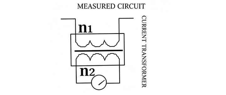
Miniature current transformers work similarly to transformers based on the principle of electromagnetic induction. Transformers convert voltage, while miniature current transformers convert current. As shown in the diagram, winding N1 is connected to the measured current, which is called a set of windings (or primary winding, primary winding); Connect winding N2 to the measuring instrument and become the secondary winding (or secondary winding, secondary winding).
The current ratio between the primary winding power I1 and the secondary winding I2 of a miniature current transformer is called the actual current ratio K. The current ratio of a miniature current transformer when operating at the rated working current is called the rated current ratio of the current transformer, expressed in Kn.
Kn=I1n/I2n
Micro current transformers can be roughly divided into measuring current transformers and protective current transformers.
A. Measurement current transformer
The measuring current transformer is mainly used in conjunction with measuring instruments to measure current, voltage, power, etc. under normal operating conditions of the circuit. The main requirements for measuring micro current transformers are: 1. Reliable insulation; 2. High enough measurement accuracy; When a high current occurs due to a fault in the side line, the transformer should saturate within an appropriate 20% (such as 500% of the rated current) to protect the measuring instrument.
B. Protective current transformer
The protective current transformer is mainly used in conjunction with the relay device to provide a signal to the relay device to cut off the faulty circuit in case of short circuit overload or other faults, in order to protect the safety of the power supply system. The working conditions of protective miniature current transformers are completely different from those of measuring transformers. Protective transformers only start working effectively at currents several times or tens of times higher than normal. The main requirements for protective transformers are: 1. Reliable insulation; 2. A sufficiently large accurate limit coefficient, 3. Adequate thermal and dynamic stability.
The maximum primary current that the protective transformer can meet the accuracy level requirements under rated load is called the rated accuracy limit primary current. The accurate limit coefficient is the ratio of the rated accurate limit current to the rated primary current. When the current is large enough, the iron core will saturate and cannot reflect the current. The accurate limit coefficient represents this characteristic. The accuracy level of the protective transformer is 5P and 10P, indicating that the allowable error at the rated accuracy limit for one current is 5% and 10%.
When a fault occurs in the circuit, the surge current generates heat and electromagnetic force, and the protective current transformer must withstand it. The effective value of the primary current that a current transformer can withstand without damage within one second in the event of a short circuit in the secondary winding is called the rated short-time current. The peak value of the primary current that the current transformer can withstand without damage in the event of a short circuit in the secondary winding is called the rated dynamic stability current.
Protective current transformers are divided into:
Overload protection current transformer
Differential protection current transformer
Grounding protection current transformer (zero sequence current transformer)
C. Micro voltage transformer
Micro voltage transformers, due to size and manufacturing reasons, usually use current type voltage transformers. In fact, it is a current transformer with a rated current ratio of 1 and both primary and secondary currents in milliampere level (e.g. 2mA/2mA):
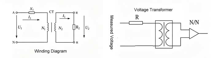
During operation, the primary winding of the transformer is connected in series with the current limiting resistor R to measure the voltage, and the secondary output is connected to the operational amplifier for I/V conversion (or direct resistance sampling). At this point, the primary current is I1=U (R+r), and the secondary current I2=I1/Kn, where r is the internal resistance of the primary winding and Kn is the rated current ratio.
Scan To Wechat :

Scan To WhatsApp :

Home
Products
contact